
By Yuhang Metal Technical Team · Updated November 2026 · 8 min read
Short answer: Order U-tubes to ASTM A213, A249 or A688 and specify the tube OD and minimum wall, a U-bend schedule (radius, leg length and quantity per row), whether bends are heat treated, and pressure testing after bending. ASTM A688 limits ovality to 10% of OD for bends of 2 × OD and larger, and sets the minimum bent wall as tf = 4RT / (4R + D).
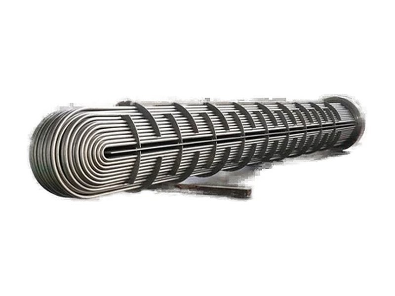
U-tube heat exchangers and feedwater heaters use tubes bent into a hairpin and expanded or welded into a single tubesheet. Each tube is free to expand on its own, so the design copes well with thermal expansion and needs no floating head. The catch is that the bend is the most heavily worked part of the tube. Cold bending thins the outer wall, flattens the tube slightly and leaves residual stress. A good U-bend specification controls all three.
Key takeaways
- Order the straight tube to a heat-exchanger specification: ASTM A213 (seamless), A249 (welded), A688 (austenitic feedwater heater tubes), A803 (welded ferritic feedwater heater tubes) or A789 (duplex).
- For bends with a centreline radius of 2 × OD or more, ASTM A688 limits ovality to 10% of the nominal OD. Tighter bends may need agreed, wider tolerances.
- A688 sets the minimum wall in the bend as tf = 4RT / (4R + D). Tight radii thin the wall more, so they may need a heavier starting wall.
- State whether the bends must be heat treated, and how every U-tube is to be pressure tested after bending.
- Send a U-bend schedule listing radius, leg length and quantity for each row.
Contents
- Step 1: Choose the base tube specification
- Related products
- Step 2: Bend radius
- Step 3: Wall thinning in the bend
- Step 4: Ovality and other U-bend tolerances
- Step 5: Heat treatment of the bend
- Step 6: Testing and cleanliness
- What to include in a U-bend tube enquiry
- Why source from Yuhang Metal
- Frequently asked questions
- References
Step 1: Choose the base tube specification
| Specification | Product | Typical application |
|---|---|---|
| ASTM A213/A213M | Seamless ferritic and austenitic alloy-steel boiler, superheater and heat-exchanger tubes | High-pressure or high-temperature exchangers |
| ASTM A249/A249M | Welded austenitic boiler, superheater, heat-exchanger and condenser tubes | General shell-and-tube exchangers and condensers |
| ASTM A688/A688M | Seamless and welded austenitic stainless steel feedwater heater tubes, U-bent when specified | Feedwater heaters and U-tube bundles |
| ASTM A803/A803M | Welded ferritic stainless steel feedwater heater tubes, such as TP439 | Feedwater heaters where ferritic grades are preferred |
| ASTM A789/A789M | Seamless and welded duplex stainless steel tubing | Chloride-bearing cooling water and process fluids |
| EN 10216-5 / EN 10217-7 | European seamless / welded stainless steel tubes for pressure purposes | Projects specified to EN standards |
These tube specifications call up the general requirements of ASTM A1016. Work under the ASME Code uses the SA- versions, such as SA-213, SA-249 and SA-688.
Related products
U-Bend Tubes
A213 / A249 / A688, legs up to 15 m
Finned Tubes
Extended-surface heat-exchange tubes
Round Tubes
Welded and seamless round tube
Step 2: Bend radius
The centreline bend radius (R) is measured to the tube axis. The tightest bend sits in the innermost row of the bundle, and each row outward has a larger radius. The tightest practical radius depends on tube OD, wall thickness, grade and bending method. Mandrel bending is used for tight radii. A tight radius of about 1.5 × OD is a common practical starting point. Note, however, that the ASTM A688 ovality limit below applies only to bends of 2 × OD and larger. If your innermost rows are tighter than that, agree the ovality and thinning acceptance values with the manufacturer at the enquiry stage.
Step 3: Wall thinning in the bend
When a tube is bent, the outside of the bend (the extrados) stretches and thins, while the inside (the intrados) thickens. ASTM A688 sets the minimum wall thickness in the bent portion as:
tf = 4RT / (4R + D). Here T is the minimum wall thickness of the straight tube, R the centreline bend radius and D the nominal OD.
Worked example for a 19.05 mm OD tube with a 1.24 mm minimum wall:
| Centreline radius R | Minimum wall in bend tf | Reduction |
|---|---|---|
| 1.5 × OD = 28.6 mm | 1.06 mm | ≈ 14% |
| 3 × OD = 57.2 mm | 1.14 mm | ≈ 8% |
If your pressure design needs a set minimum wall in the bend, work backwards: T = tf × (4R + D) / 4R. Then order the innermost rows with that heavier wall, or use a larger radius.
Step 4: Ovality and other U-bend tolerances
For a centreline bend radius of 2 × D or greater, ASTM A688 requires that the major and minor diameters in the bend do not deviate from the nominal OD by more than 10%. For a 19.05 mm tube, that is roughly 17.1–21.0 mm. A688 also sets the following tolerances. The figures are from the 2015 edition, so check the edition named on your order.
| Item | ASTM A688 requirement |
|---|---|
| Leg length | Never shorter than specified. Plus tolerance of 1/8 in (3.2 mm) up to 20 ft, 5/32 in (4.0 mm) over 20–30 ft, and 3/16 in (4.8 mm) over 30–40 ft |
| Difference between the two legs | Not more than 1/8 in (3 mm) unless otherwise specified |
| Leg spacing (2R − OD) | ±1/16 in (1.5 mm) of nominal |
| Plane of bend | Deviation not more than 1/16 in (1.5 mm), measured from the points of tangency |
| Bend curvature | Substantially uniform |
Step 5: Heat treatment of the bend
Cold bending work-hardens the bend and leaves residual stress. That raises the risk of stress corrosion cracking in chloride or caustic service, so many purchasers require the bends to be heat treated, at least on the tightest rows. Where U-bend heat treatment is specified, ASTM A688 requires:
- Solution annealing at 1040 °C (1900 °F) minimum, followed by rapid cooling
- Treatment of the bend plus about 150 mm (6 in) of each leg beyond the tangent point
- Temperature control by optical or emission pyrometer, with no temperature-indicating crayons or lacquers
- An inert or protective gas purge inside the tube until it has cooled below 370 °C (700 °F)
- Inspection of electrode contact areas for arc burns when resistance heating is used
State on the U-bend schedule which rows need heat treatment, for example all bends below a given radius.
Step 6: Testing and cleanliness
- After bending: ASTM A688 requires every U-tube to be pressure tested after bending and after any heat treatment of the bend. This can be a hydrostatic test, or a pneumatic test (air underwater or pneumatic leak test) as the purchaser specifies.
- Straight tube: eddy current testing before bending, with ultrasonic thickness checks and ovality measurement on sample bends.
- Cleanliness: bending lubricant must be removed. A688 checks inside cleanliness by blowing acetone-soaked felt plugs through 10% of the tubes of each bend radius.
- Test water: use low-chloride water for hydrostatic tests of austenitic tubes, then drain and dry them.
What to include in a U-bend tube enquiry
- Specification and grade, for example ASTM A688 TP304L or A213 TP316L
- Tube OD × minimum or average wall, and wall for any tight inner rows
- U-bend schedule: row number, centreline radius, leg length and quantity per row
- Heat treatment of bends: which rows, and the method
- Test method after bending (hydrostatic or pneumatic) and NDE on straight tube
- End finish, cleanliness, packing (supported by row in wooden cases) and EN 10204 3.1 certificates
See our U-bend tubes and other stainless steel pipes and tubes, read the ASTM pipe and tube standards comparison, or send us your U-bend schedule for a quotation.
Why source from Yuhang Metal
- Stainless steel supplier based in Foshan, Guangdong, since 1986. In 1988 we commissioned China’s first stainless steel high-frequency welded pipe mill.
- U-bend tubes from 9.52 to 38.1 mm OD and 0.7–3.0 mm wall, with leg lengths up to 15 m and bend radii from 1.5 × OD.
- Hydrostatic testing after bending, eddy current testing, and ovality and thinning checks on the bends. Stress relieving of the bend area is available on request.
- EN 10204 3.1 certificates.
Frequently asked questions
What is the minimum bend radius for stainless steel U-tubes?
It depends on tube OD, wall thickness, grade and bending method. A tight radius of about 1.5 × OD is a common practical starting point. The ASTM A688 ovality limit of 10% applies only to bends of 2 × OD or larger, so tolerances for tighter bends should be agreed with the manufacturer.
How much does the wall thin in a U-bend?
ASTM A688 sets the minimum wall in the bend as tf = 4RT / (4R + D). For a 19.05 mm OD tube with a 1.24 mm minimum wall, that is about 1.06 mm at 1.5 × OD radius (around 14% thinner) and 1.14 mm at 3 × OD radius (around 8% thinner).
Do U-bends need heat treatment?
Not always, but it is common for tight bends in chloride or caustic service, where residual stress from cold bending increases the risk of stress corrosion cracking. When specified under ASTM A688, the bend and about 150 mm of each leg are solution annealed at 1040 °C minimum and rapidly cooled.
Are U-tubes pressure tested after bending?
Under ASTM A688, every U-tube is pressure tested after bending and after any heat treatment of the bend, by a hydrostatic or pneumatic test as specified by the purchaser.
Can welded tubes be U-bent?
Yes. ASTM A688 covers both seamless and welded austenitic feedwater heater tubes bent into U-tubes, and welded A249 tubes are also widely used in U-tube bundles. The tube must meet the specification’s tests before bending.
What is leg spacing on a U-tube?
Leg spacing is the gap between the two legs, equal to twice the centreline radius minus the tube OD (2R − OD). ASTM A688 allows ±1/16 in (1.5 mm) on the nominal value.
What sizes of U-bend tube can Yuhang Metal supply?
We supply U-bend tubes from 9.52 to 38.1 mm OD with 0.7–3.0 mm wall, leg lengths up to 15 m, and bend radii from 1.5 × OD, in grades including 304/304L, 316L, 321, 439, 2205, 2507 and 904L.
References
- ASTM A688/A688M – Seamless and welded austenitic stainless steel feedwater heater tubes
- ASTM A213/A213M, A249/A249M, A803/A803M, A789/A789M
- ASTM A1016/A1016M – General requirements for ferritic alloy, austenitic alloy and stainless steel tubes
- EN 10216-5 and EN 10217-7